so-you-think-you-can-code-2025
Building a Real-Time WGSL Shader Playground with WebGPU and WebRTC
Category: 🌐 Web Projects
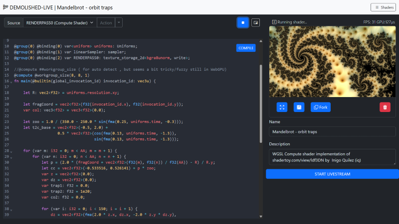
I’ve built a live-coding environment that lets the user instantly compile WebGPU Shading Language (WGSL) directly from the editor, render the result to a canvas, and broadcast that canvas output in real-time using WebRTC. This post briefly describes the building blocks that makes this ambitious real-time workflow possible. The source code is shared in total in an external repository. (found later on in this post)
The editor can be tested at the following URL: https://magnusthor.github.io/demolished-live-code/public/(Note: Live stream features require cloning the repository and running the server locally or in your own server environment).
Stack Highlights:
I built this application using JavaScript/Node.js stack, leveraging key low- browser APIs:
| Component | Technology | Role |
|---|---|---|
| Backend / Signaling | Node.js, Express, thor-io.vnext |
Handles initial WebRTC signaling for peer connections |
| Editor / UI | CodeMirror 6, TypeScript | Provides the WGSL editor with syntax highlighting and manages the compilation loop |
| GPU Engine | WebGPU, TypeScript (WGSLShaderRenderer) |
Compiles and executes the WGSL code on the GPU |
| Streaming | WebRTC, Canvas captureStream |
Captures the GPU output and streams it peer-to-peer, combined with mic/cam/screen. |
The Core Architecture - A Triple Threat
The application’s functionality is achieved through the seamless integration of three primary systems/components: the Code Editor, the WebGPU Renderer, and the WebRTC Streamer.
A. The Interactive Editor: CodeMirror & Compile Flow
The editor, built with CodeMirror 6, is more than just a text box. It manages the vital parts of development lifecycle / experience.
-
WGSL Syntax: I gain robust syntax highlighting and structure by utilizing the Rust language extension (
@codemirror/lang-rust), given WGSL’s strong influence from the Rust programming language. -
The Compilation Loop (
Editor.onCompile): This function is the nerve center of the feedback loop.- The user’s code is extracted from the CodeMirror component
-
The code is passed to
tryCompilewhich calls the crucial GPU validation step:// The real-time compiler check using the WebGPU API const shaderModule = this.renderer.device.createShaderModule({ code: source }); const compileError: IError = { // ... errors: await shaderModule.getCompilationInfo(), } - If
getCompilationInfo()reports errors, the editor uses a custom decorator to draw immediate visual feedback right next to the corresponding line number.
The Engine - Dynamic WebGPU Rendering
The WGSLShaderRenderer class is responsible for taking the compiled WGSL code and executing it in real-time. The playground supports the entire WebGPU rendering pipeline, enabling both Fragment (rendering) and Compute (data processing) shaders.
A. Building the Pipeline (The Main Render Pass) and Multi-Pass Shader Graph
The core architectural strength lies in the support for a Multi-Pass Shader Graph—the ability to dynamically define and combine $1-N$ Compute and Fragment passes into a processing chain. This approach allows for sophisticated, multi-stage effects and GPGPU workflows.
-
Arbitrary Shader Chaining: Each pass (whether Compute or Fragment) renders its result to a unique output texture resource (
RENDERPASS0,RENDERPASS1, etc.). This resource can then be bound as a sampler input to any subsequent pass. This creates a flexible graph structure, allowing users to define complex workflows like: Compute Simulation → Fragment Post-Process → Fragment Final Output. -
Final Output Blit: The final rendering to the canvas is handled by a specialized, simple “Main Fragment” shader. Its primary job is to perform a texture blit—it samples the output texture of the very last pass in the dynamic chain and writes that result to the final presentation canvas. The system dynamically updates the resource binding (
@binding(2) var RENDERPASS0: texture_2d<f32>;) to point to the correct final texture.The structure of the final blit shader is:
// Main Fragment Blit Stage
struct Uniforms {
  resolution: vec3<f32>,
  time: f32
};
@group(0) @binding(0) var screen_sampler : sampler;
@group(0) @binding(1) var<uniform> uniforms: Uniforms;
@group(0) @binding(2) var RENDERPASS0: texture_2d<f32>; // Dynamically bound to the final texture in the chain

struct VertexOutput {
  @builtin(position) Position: vec4<f32>,
  @location(0) TexCoord: vec2<f32>
};

@fragment
fn main_fragment(@location(0) TexCoord : vec2<f32>,@builtin(position) Position: vec4<f32> ) -> @location(0) vec4<f32> {
  return  textureSample(RENDERPASS0, screen_sampler, TexCoord);
}
B. Executing the Workload (update and Compute Dispatch)
Every frame, the update method orchestrates the rendering flow using a GPUCommandEncoder.
-
Compute First: Compute shaders (added via
addComputeRenderPass) run first. The work is efficiently distributed by calculating the dispatch size based on the canvas size and the compute shader’s workgroup dimensions.// Workload distribution for Compute Shaders computePassEncoder.dispatchWorkgroups( Math.ceil(this.canvas.width / computeRenderPass.workgroupSize!.x), Math.ceil(this.canvas.height / computeRenderPass.workgroupSize!.y), computeRenderPass.workgroupSize!.z ); - Fragment Rendering: Subsequently, intermediate fragment shaders and the final
- Main Fragment Blit Stage execute, drawing the results to the
#result-canvas.
Note: Worth looking at is this file in the source code repo
https://github.com/MagnusThor/demolished-live-code/blob/master/src/engine/renderer/webgpu/wgslShaderRenderer.ts
Shader Execution Models
The most crucial architectural decision for the WGSLShaderRenderer is supporting two fundamentally different execution models: Compute and Fragment shaders. While both utilize the parallelism of the GPU, they differ in purpose, input, output, and control.
A. Compute Shader: Explicit Control and Data Manipulation
Compute shaders are general-purpose programs executed on the GPU, often used for physics simulation, data processing, or generating textures before or between the rendering stages.
-
Control: The developer has explicit control over how the workload is organized using workgroups.
-
Input/Output: Data is typically read from and written to storage buffers or storage textures using explicit functions like
textureLoadandtextureStore. The shader below writes its output toRENDERPASS0. -
Thread ID: The shader uses
@builtin(global_invocation_id)to know its position in the overall workload grid.
Stub: Compute Shader
@group(0) @binding(2) var RENDERPASS0: texture_storage_2d<bgra8unorm, write>;

@compute @workgroup_size(8, 8, 1) // Dynamic workgroup size applies here
fn main(@builtin(global_invocation_id) invocation_id: vec3u) {
  let R: vec2<f32> = uniforms.resolution.xy;
  let fragCoord = vec2<f32>(f32(invocation_id.x), f32(invocation_id.y));
  var col: vec3<f32> = vec3<f32>(0.0);

  // ... (do the magic) ...

  // Explicitly write the calculated color to the storage texture
  textureStore(RENDERPASS0, invocation_id.xy, vec4<f32>(col, 1.0));
}
Dynamic Workgroup Sizing for Usability
To make the Compute Shader experience seamless, the renderer automatically calculates and injects the @workgroup_size attribute if the user omits it. This is done by querying the GPU’s supported limits:
export const getWorkgroupSizeString = (limits: GPUSupportedLimits): {
    // ...
    workgroup_size: string
} => {
    // Finds a safe power-of-two size, respecting device limits.
    const x = Math.min(16, largestPowerOf2LessThan(limits.maxComputeWorkgroupSizeX));
    const y = Math.min(16, largestPowerOf2LessThan(limits.maxComputeWorkgroupSizeY));
    return {
        x: x, y, z: 1, workgroup_size: `@workgroup_size(${x}, ${y}, 1)`
    };
}
B. Fragment Shader: Automatic Per-Pixel Execution (Intermediate Pass)
Fragment shaders are executed as a step in the multi-pass graphics pipeline, specifically for determining the color and properties of a single pixel (or fragment), writing the output to a texture resource for subsequent passes to consume.
-
Control: Thread distribution is automatic, dictated by the rendering system (the rasterizer). It executes once per fragment generated by the vertex stage.
-
Input/Output: The shader’s function simply returns a color value, and the graphics pipeline automatically writes that color to the current pass’s render target (which is typically a texture resource in this multi-pass architecture).
-
Thread ID: The shader typically uses the
in.pos.xycoordinate, passed from the vertex shader, to get its screen location.
Stub : Fragment Shader
@fragment
fn main_fragment(in: VertexOutput) -> @location(0) vec4<f32> {
  // Uses the position from the vertex stage to calculate pixel color
  return mainImage(in.pos.xy);
}

fn mainImage(invocation_id: vec2<f32>) -> vec4<f32> {
  let fragCoord = vec2<f32>(f32(location.x), f32(location.y) );
  let uv: vec2<f32> = fragCoord.xy / uniforms.resolution.xy - 0.5;

  // ... (color calculation) ...

  // Returns the calculated color, which is automatically written to the current pass's output texture
  return  vec4<f32>(vec3<f32>(color, color * 0.5, sin(color + time / 3.) * 0.75), 1.);
}
Summary of Differences
| Feature | Compute Shader | Fragment Shader |
|---|---|---|
| Purpose | General-purpose data processing, simulation, texture generation | Coloring pixels (fragments) during the rendering stage |
| Workload Control | Explicit via @workgroup_size and dispatchWorkgroups |
Implicit; automatic per-pixel execution by the rasterizer |
| Output | Explicit write to storage textures/buffers using textureStore |
Implicit return value written automatically to the render target |
| Entry Point | @compute fn main(...) |
@fragment fn main_fragment(...) |
Note: When you run the demo, a set of default shaders will be set up automatically, so i suggest you have a look there if of interest. https://magnusthor.github.io/demolished-live-code/public/
Real-Time Broadcast with the LiveStreamComponent
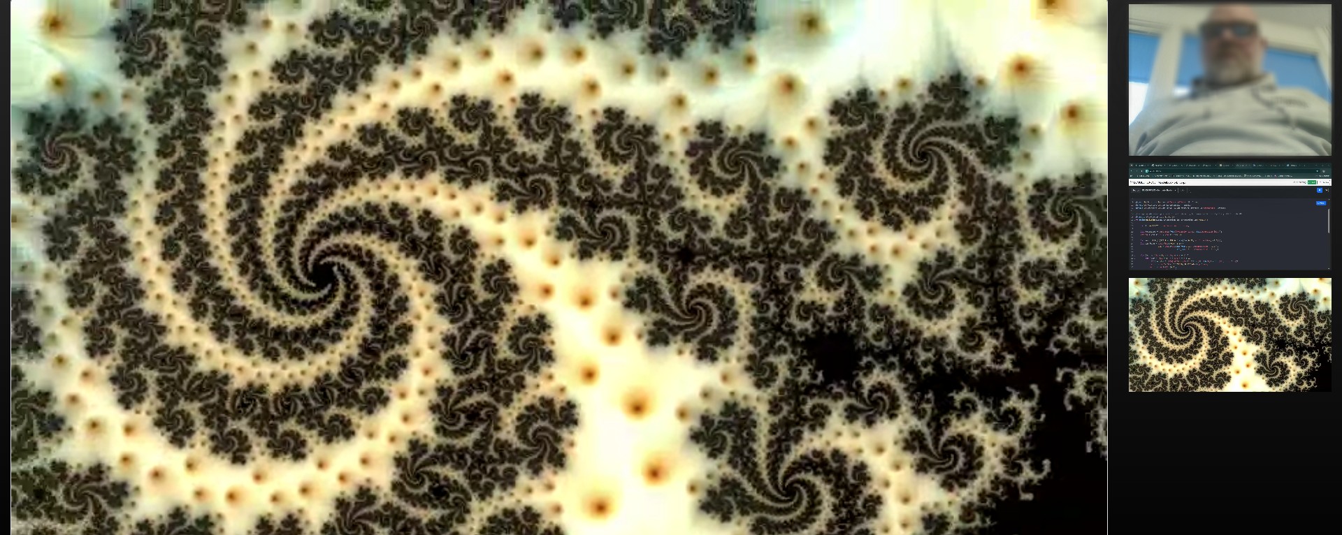
Next thing we dig into is the broadcaster, the LiveStreamComponent, which seamlessly merges the WebGPU output with real-world media streams and broadcasts them using WebRTC.
A. Multi-Source Stream Composition
The LiveStreamComponent shows the power of the MediaStream API combined with WebRTC. It takes multiple distinct sources and combines them into a single local stream for transmission:
-
WebGPU Output: The core shader result is captured as a video track directly from the
#result-canvasusing thecaptureStreammethod, ensuring the GPU’s real-time output is included in the media stream:// Capture the WebGPU-rendered canvas output const outputVideoTrack = this.compositionCanvas.captureStream(fps).getVideoTracks()[0]; combinedStream.addTrack(outputVideoTrack); -
Webcam & Microphone: User-selected devices are accessed via standard
navigator.mediaDevices.getUserMedia(constraints). -
Screen Share: The entire screen, a window, or a tab is captured using the browser’s native prompt via
navigator.mediaDevices.getDisplayMedia.
These individual tracks are then combined into a combinedStream which becomes the source for the WebRTC connection.
B. WebRTC Transport Architecture (P2P vs. MCU/SFU)
It is critical to note that the WebRTC connection established here is Peer-to-Peer (P2P). This approach is highly effective for low-latency, secure communication among small, cooperative teams and scenarios where involving third-party media servers is undesirable.
-
Scalability Consideration: For large-scale broadcasting (e.g., streaming to dozens or hundreds of spectators), a pure P2P architecture is resource-intensive on the broadcaster’s machine.
-
Real-World Evolution: In a commercial or large-scale broadcast scenario, the architecture would evolve to utilize a Media Control Unit (MCU) or a Selective Forwarding Unit (SFU). This media server sits between the broadcaster and the spectators, offloading the load and potentially enabling distribution via standard HTTP video streaming formats (like HLS or DASH). The current P2P model serves as the ideal baseline for small-team collaboration and minimal overhead.
I use the thor-io.client-vnext library and its WebRTCFactory to manage the underlying P2P WebRTC connections.
-
The local
combinedStreamis passed to the factory:this.rtcFactory?.addLocalStream(combinedStream); -
A unique stream URL is generated using a
streamUUIDfor the Spectator view. This URL follows a pattern:window.location.href}spectate/#${this.streamUUID} -
The broadcaster joins a dedicated context/room using the UUID:
this.rtcFactory?.changeContext(this.streamUUID); -
The
rtcFactorythen handles the low-level Signaling (SDP Offer/Answer exchange) and initiates the secure, peer-to-peer media transport. TheLiveStreamComponentis designed purely as a broadcaster, so it expects no remote streams, explicitly logging:console.log('We will not be receiving any remote streams, but broadcast').
The Spectator view - Consuming the Stream
The SpectatorClient is responsible for reversing the process: connecting to the signaling server, joining the room defined by the URL hash, and consuming the multi-track stream broadcast by the coder.
Initialization and Joining the Context
The client first parses the streamUUID from location.hash. It then initializes the ClientFactory to connect to the signaling server. The key action is triggered when the user clicks the “JOIN LIVESTREAM” button:
// SpectatorClient.render()
DOMUtils.on("click", joinButton, () => {
    this.rtcFactory?.changeContext(this.streamUUID);
    // ...
});
Calling changeContext(this.streamUUID) instructs the signaling server to connect this spectator client to the dedicated WebRTC room, initiating the SDP handshake to receive the stream.
Handling Incoming Media Tracks (onRemoteTrack)
Since the broadcaster sends a single stream containing separate tracks (GPU video, camera video, and audio), the spectator must process each track individually using the onRemoteTrack event:
-
Video Tracks (GPU/Camera/Screen): Each video track is wrapped in its own
new MediaStream(). A thumbnail (video-thumb) is rendered in the sidebar for selection. The spectator can click a thumbnail to assign its stream to the main#selected-video-streamplayer.this.rtcFactory.onRemoteTrack = (mediaStreamTrack: MediaStreamTrack, remoteConnection: ThorIOConnection, rtcEvent: RTCTrackEvent) => { if (mediaStreamTrack.kind === "video") { const newMediaStream = new MediaStream(); newMediaStream.addTrack(mediaStreamTrack); this.renderVideoElement(newMediaStream); // Renders the thumbnail } // ... }; -
Audio Tracks (Microphone): The audio track is separated and routed directly to a hidden
<audio>element for playback. The use ofoncanplayandplay()handles browser autoplay policies.} else if (mediaStreamTrack.kind === "audio") { const audioElement = DOMUtils.get<HTMLAudioElement>("#speaker-audio"); const audioStream = new MediaStream([mediaStreamTrack]); audioElement.srcObject = audioStream; audioElement.oncanplay = () => { audioElement.play(); }; }
Stream Lifecycle Management
The SpectatorClient manages the addition and removal of streams using mediaStreamTrack.onended and the handleTrackLost method. When a track ends (e.g., the coder stops screen sharing or closes the tab), the corresponding thumbnail is removed from the DOM, and the main video player automatically switches to a remaining stream if available, ensuring a robust viewing experience.
The entire system—from the real-time WGSL compilation on the GPU to the peer-to-peer consumption of the composite stream—demonstrates a powerful, low-latency approach to collaborative, live-coded graphics.
Running the Project Locally
Note: This is not a complete application, but shows in rough outlines how it might work. As time permits, I will clean up and complete with the missing things.
The complete source code for this project is available for cloning from this repository https://github.com/MagnusThor/demolished-live-code. To set up and run the environment locally:
-
Clone the Repository:
git clone https://github.com/MagnusThor/demolished-live-code.git demolished-live-code cd demolished-live-code -
Install Dependencies:
npm install -
Build the Project: (Note: The project uses TypeScript and Webpack for building, so a dedicated build step is necessary before starting the Node.js server.)
npm run build -
Start the Server:
npm start
This will launch the application on http://localhost:1337, allowing you to experience the real-time WGSL live-coding and streaming environment first-hand.
Thanks for your time, hope it was interesting and not too confusing Magnus